Real-Time Video Post-Processing on Android with OpenGL ES Fragment Shaders
Every modern video player on Android eventually does the same thing: feeds compressed video into MediaCodec, lets the hardware decoder turn it into raw frames, and pushes those frames to a Surface for display. The entire process is optimized to be invisible. And for 99% of use cases, that is exactly what you want.
But what if you want to touch the pixels before they reach the screen?
Real-time color grading, sharpening, low-light enhancement. Movie editors do these in DaVinci Resolve at thousands of dollars per seat. Doing them on a mobile phone, at 60fps, on hardware ranging from flagship Snapdragons to budget MediaTek chips, requires an entirely different set of trade-offs.
This post covers how to build a real-time video post-processing pipeline on Android using OpenGL ES 2.0 fragment shaders: intercepting the video pipeline via SurfaceTexture, designing a permutation-based shader architecture, implementing color grading and AMD CAS sharpening, building a low-light mode with bilateral denoising and ACES tone mapping, and handling DRM protected content and HDR transfer functions.
Intercepting the Android Video Pipeline
The Standard Path
In the normal Android video rendering path, the flow is straightforward:
MediaCodec decodes a frame into a hardware buffer. That buffer is sent directly to SurfaceFlinger (Android’s system compositor) via the Surface. At no point does the CPU or your application code see the raw pixels. The entire pipeline is zero-copy, hardware-accelerated, and (importantly) opaque.
The Intercepted Path
To manipulate pixels before display, we replace the opaque Surface with a SurfaceTexture. A SurfaceTexture is the bridge between the Android BufferQueue and OpenGL ES: it receives the hardware-decoded frame and exposes it as a GL texture.
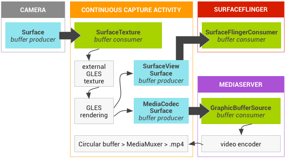
Step ③ is where the magic happens. We write a custom GLSL fragment shader that samples the decoded frame from the texture, applies our color grading math, and outputs the result to the GLSurfaceView’s default framebuffer.
Why GL_TEXTURE_EXTERNAL_OES?
Android’s SurfaceTexture does not produce a standard GL_TEXTURE_2D. Instead, it uses GL_TEXTURE_EXTERNAL_OES, a special texture target defined by the OES_EGL_image_external extension. This has practical implications:
- Your fragment shader must declare
#extension GL_OES_EGL_image_external : require - You must use
samplerExternalOESinstead ofsampler2D - The texture transform matrix from
SurfaceTexture.getTransformMatrix()must be applied in the vertex shader, because the hardware may store the frame in any orientation or format (YUV, tiled, etc.)
#extension GL_OES_EGL_image_external : require
precision mediump float;
uniform samplerExternalOES videoTexture;
varying highp vec2 v_TexCoord;

void main() {
    vec4 color = texture2D(videoTexture, v_TexCoord);
    // ... apply enhancement ...
    gl_FragColor = color;
}
Why Not AGSL?
Android 13 introduced AGSL (Android Graphics Shading Language) and RenderEffect, which can apply GPU shaders to any View. While AGSL is great for UI effects like blurs and rounded corners, it is not suitable for a video post-processing pipeline:
- No EGL control: you cannot configure secure EGL contexts for DRM content
- No SurfaceTexture integration: AGSL works on rendered View bitmaps, not raw video textures
- Backward compatibility: AGSL requires API 33+, while
GL_OES_EGL_image_externalworks on API 14+ - Per-frame control: the
GLSurfaceView.Renderercallback gives you deterministic per-frame timing; AGSL is tied to the View rendering schedule
Shader Architecture: Permutation-Based Design
The Cost Model
On mobile GPUs, the dominant performance bottleneck for full-screen image processing is texture fetches, not arithmetic. Each texture2D() call issues a memory read from VRAM, which is orders of magnitude slower than an ALU (arithmetic) operation:
| Operation | Relative Cost (mobile GPU) |
|---|---|
| ALU (add, multiply, pow) | 1x |
texture2D() from cache | ~10-20x |
texture2D() cache miss | ~100-200x |
A 4K frame has 8.3 million fragments. If your shader does 14 texture fetches per fragment (e.g., 5 for sharpening + 9 for denoising), that is 116 million texture reads per frame. At 60fps, that is 7 billion reads per second. Texture fetch count is the single most important optimization lever.
Shader Permutations: Lightweight vs Full
The key insight is that not all enhancement features need neighborhood sampling. Color grading operations (brightness, contrast, saturation, vibrance, gamma, color temperature) are all point operations: they depend only on the current pixel’s value. They require exactly 1 texture fetch.
Sharpening (CAS) and denoising (Night Vision), on the other hand, are neighborhood operations: they sample surrounding pixels. CAS needs 5 fetches; bilateral denoise needs 9.
Rather than using a single uber-shader with if branches (which cause warp divergence on mobile GPUs), we compile two shader permutations (a lightweight variant and a full variant) and switch between them at draw time:
Lightweight Variant
Condition: sharpness ≈ 0 AND !nightVisionFetches: 1 (center only)
Operations: Color grading only
Cost: ~0.3ms @ 4K
Full Variant
Condition: sharpness > 0 OR nightVisionFetches: 5–14
Operations: CAS + denoise + color grading
Cost: ~1.5–3.5ms @ 4K
This means that when the user is only using color grading (brightness, contrast, etc.), the GPU does 1 texture fetch per fragment, essentially free. The expensive neighborhood operations are only paid for when sharpening or Night Vision is actually enabled.
The Color Grading Pipeline
Color grading is the core of the enhancement system. All six operations are point operations that sample only the center pixel, and they are applied in a specific order that matters.
Processing Order
brightness → contrast → saturation → vibrance → temperature → gamma
Each stage’s output feeds into the next. The order is not arbitrary:
- Brightness first, because it shifts the working range for all subsequent operations
- Contrast before saturation, because contrast adjustment changes the perceived saturation
- Saturation before vibrance, because vibrance is selective saturation that needs to know how saturated the pixel already is
- Temperature before gamma, because gamma correction should be the last perceptual adjustment
Stage 1: Brightness
The simplest operation. A uniform offset applied to all channels:
c += vec3(u_Brightness); // range: [-1.0, 1.0]
This is a linear shift in code value. A brightness of +0.1 adds 0.1 to every channel regardless of the original value. Simple, but crude. It can clip highlights. More sophisticated approaches use curves, but for a real-time mobile pipeline, the simplicity is worth the trade-off.
Stage 2: Contrast (S-Curve)
This is where it gets interesting. There are two common approaches to contrast adjustment:
Linear pivot: (c - 0.5) * k + 0.5
This simply scales pixel values around the midpoint. The problem is clipping: values below 0.5 - 0.5/k are crushed to black, and values above 0.5 + 0.5/k are blown to white. At high contrast settings, you lose shadow and highlight detail.
S-curve (power function): 0.5 * pow(c / 0.5, k)
This produces a smooth sigmoidal curve that compresses shadows and highlights gradually instead of clipping them. The midpoint (0.5) is preserved, shadows get darker, highlights get brighter, but neither clips abruptly.
// S-curve contrast: smooth rolloff, no clipping
c = 0.5 * pow(max(c / 0.5, 0.0), vec3(u_Contrast));  // k=1.0 = identity
The max(..., 0.0) guards against negative values from the brightness stage. When u_Contrast = 1.0, this is the identity function: 0.5 * pow(c/0.5, 1.0) = c.
Stage 3: Saturation
Saturation controls the intensity of color. The technique is standard: mix between the pixel’s luminance (grayscale) and its full color:
float luma = dot(c, vec3(0.2126, 0.7152, 0.0722));  // BT.709
c = mix(vec3(luma), c, u_Saturation);  // 0.0 = grayscale, 1.0 = original, 2.0 = oversaturated
The luminance coefficients [0.2126, 0.7152, 0.0722] are the BT.709 standard, the same used in sRGB. These are not arbitrary: they reflect the human eye’s spectral sensitivity, with green contributing the most to perceived brightness.
Stage 4: Vibrance (Selective Saturation)
Vibrance is a more intelligent version of saturation, popularized by Adobe Lightroom. Instead of boosting all colors equally, it selectively boosts less-saturated colors more than already-saturated ones. This prevents skin tones and bright colors from becoming unnaturally vivid.
float maxC = max(c.r, max(c.g, c.b));
float minC = min(c.r, min(c.g, c.b));
float chroma = maxC - minC;  // 0 = gray, 1 = fully saturated
c = mix(vec3(luma), c, 1.0 + u_Vibrance * (1.0 - chroma));
The key is (1.0 - chroma): when a pixel is already highly saturated (chroma close to 1), the boost factor approaches 0. When a pixel is nearly gray (chroma close to 0), it gets the full vibrance boost. This is the same principle behind GPUImage’s Vibrance filter.
Stage 5: Color Temperature
A simple but effective approximation of white balance adjustment using channel scaling:
c.r *= 1.0 + 0.2 * u_Temperature;  // positive = warmer (more red)
c.b *= 1.0 - 0.2 * u_Temperature;  // negative = cooler (more blue)
A proper white balance adjustment would work in a color space like CIE xy and modify the illuminant along the Planckian locus. But for a real-time mobile shader, R/B channel scaling is perceptually close enough and costs just 2 multiply-adds.
Stage 6: Gamma
The final adjustment. Gamma correction controls the overall brightness curve:
c = pow(max(c, 0.0), vec3(1.0 / max(u_Gamma, 0.001)));
Gamma > 1.0 brightens midtones (useful for dark scenes). Gamma < 1.0 darkens midtones (useful for faded/vintage looks). The max(u_Gamma, 0.001) prevents division by zero in the exponent.
Putting It All Together
Here is the complete color grading pipeline in GLSL:
// Color grading pipeline (point operations only — 0 extra texture fetches)
vec3 W = vec3(0.2126, 0.7152, 0.0722);  // BT.709 luminance

c += vec3(u_Brightness);                                          // 1. Brightness
c = 0.5 * pow(max(c / 0.5, 0.0), vec3(u_Contrast));             // 2. S-curve contrast
float luma = dot(c, W);
c = mix(vec3(luma), c, u_Saturation);                             // 3. Saturation
float maxC = max(c.r, max(c.g, c.b));
float minC = min(c.r, min(c.g, c.b));
c = mix(vec3(luma), c, 1.0 + u_Vibrance * (1.0 - (maxC - minC)));// 4. Vibrance
c.r *= 1.0 + 0.2 * u_Temperature;                                // 5. Temperature
c.b *= 1.0 - 0.2 * u_Temperature;
c = pow(max(c, 0.0), vec3(1.0 / max(u_Gamma, 0.001)));          // 6. Gamma
All six operations are pure ALU with no additional texture fetches, no branches. On a modern mobile GPU, this entire pipeline costs roughly 20 ALU operations per fragment.
Content-Adaptive Sharpening (AMD CAS)
The Problem with Unsharp Mask
The traditional approach to image sharpening is the Unsharp Mask: subtract a blurred version of the image from the original, then add the difference back scaled by a strength factor. The problem is halo artifacts, bright rings around dark edges and dark rings around bright edges.
Halos occur because the Unsharp Mask blindly amplifies all local differences, including high-contrast edges where the amplification produces visible overshoots. The stronger the sharpening, the worse the halos.


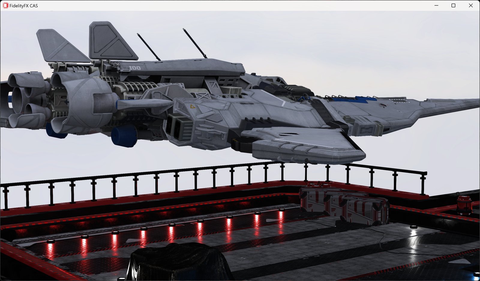
How CAS Works
AMD’s Contrast Adaptive Sharpening (CAS), part of the FidelityFX suite, solves this problem elegantly. Instead of a fixed sharpening kernel, CAS dynamically adjusts its strength based on the local contrast of each pixel:
- Sample a 5-tap cross pattern: center + 4 axis-aligned neighbors (top, bottom, left, right)
- Compute local min/max per color channel across the 5 samples
- Calculate an adaptive weight using the ratio of min to max
- Apply sharpening using the weight: high contrast edges get less sharpening

The key formula is the adaptive weight calculation:
$$w = \sqrt{\min\left(\frac{mn}{mx},\; \frac{1 - mx}{1 - mn}\right)}$$where $mn$ and $mx$ are the local minimum and maximum values for each color channel. This produces a weight between 0 and 1:
- Low contrast (mn ≈ mx) → $mn/mx$ ≈ 1.0 → strong sharpening
- High contrast (mn ≪ mx) → $mn/mx$ ≈ 0.0 → weak sharpening (halo suppression)
- Near white (mx ≈ 1.0) → $(1-mx)/(1-mn)$ ≈ 0.0 → weak sharpening (highlight protection)
This is why CAS is “content-adaptive”. It automatically reduces sharpening on hard edges where halos would be most visible, while maximizing sharpening in fine-detail areas where it improves perceived clarity.
GLSL Implementation
// AMD FidelityFX CAS v1.0 (MIT License)
// 5-tap cross pattern with content-adaptive weighting
vec3 applyCAS(vec3 center, highp vec2 uv) {
    // Sample 4 neighbors (4 texture fetches)
    vec3 a = texture2D(videoTexture, uv + vec2( 0.0, -texelSize.y)).rgb;  // top
    vec3 b = texture2D(videoTexture, uv + vec2(-texelSize.x,  0.0)).rgb;  // left
    vec3 d = texture2D(videoTexture, uv + vec2( texelSize.x,  0.0)).rgb;  // right
    vec3 e = texture2D(videoTexture, uv + vec2( 0.0,  texelSize.y)).rgb;  // bottom

    // Per-channel local min/max
    float mnR = min(min(a.r, min(b.r, center.r)), min(d.r, e.r));
    float mxR = max(max(a.r, max(b.r, center.r)), max(d.r, e.r));
    // ... (same for G and B)

    // Adaptive weight: sqrt(min(mn/mx, (1-mx)/(1-mn)))
    float wR = sqrt(min(mnR / (mxR + 1e-5), (1.0 - mxR) / (1.0 - mnR + 1e-5)));
    // ... (same for G and B)

    // Map sharpness [0, 1] to peak lobe weight [0, -0.2]
    // AMD CAS original: peak = -1/(8 - 3*sharpness), range -0.125 to -0.2
    float peak = mix(0.0, -0.2, u_Sharpness);
    wR *= peak;

    // Weighted average (negative weight = sharpening)
    return vec3(
        (a.r*wR + b.r*wR + center.r + d.r*wR + e.r*wR) / (1.0 + 4.0*wR),
        // ... (same for G and B)
    );
}
CAS is applied before color grading in the pipeline. This is important: sharpening should work on the original luminance relationships, not on color-corrected values. The pipeline is:
texture fetch → CAS → Night Vision → color grading → output
This contrasts with a common mistake in naive implementations where color grading operations (brightness, contrast, saturation) are applied to neighbor pixels too. Since sharpening is based on luminance differences between pixels, applying color correction to neighbors is wasted work because it does not change the relative differences that drive the sharpening.
CAS vs Unsharp Mask: Comparison
| CAS | Unsharp Mask | |
|---|---|---|
| Texture fetches | 5 (cross) | 5-9 (cross or 3×3) |
| Halo artifacts | None (adaptive suppression) | Visible at high strength |
| Content-adaptive | Yes (min/max ratio) | No (fixed kernel) |
| Fine detail | Excellent preservation | Good |
| License | MIT (AMD FidelityFX) | N/A |
Night Vision: Low-Light Enhancement
Enhancing dark video in real-time is one of the hardest problems in mobile image processing. If you simply increase brightness uniformly, three things go wrong:
- Noise amplification: dark regions in video are dominated by sensor noise. Boosting brightness amplifies the noise proportionally.
- Highlight clipping: already-bright areas (streetlights, screens) blow out to pure white.
- Color shift: linear brightness scaling desaturates colors as they approach the clipping boundary.
The Night Vision pipeline addresses all three problems with a three-stage approach:
Stage 1: Adaptive Exposure Boost
Instead of boosting brightness uniformly, we apply an exposure function that adapts to the local luminance. Dark pixels get a stronger boost; bright pixels get little to no boost.
float L = dot(color, vec3(0.2126, 0.7152, 0.0722));
float exposureBoost = mix(3.0, 0.0, smoothstep(0.0, 0.4, L));  // 0-3 EV
float exposureMul = pow(2.0, exposureBoost * strength);          // 1x-8x
vec3 boosted = color * exposureMul;
The smoothstep(0.0, 0.4, L) function creates a smooth transition: pixels with luminance below 0.0 get the full +3 EV boost (8x brightness), pixels above 0.4 get no boost, and the transition is gradual. This is the key to preserving highlights while lifting shadows.
Stage 2: Bilateral Denoise (3×3)
After boosting exposure, noise in the dark regions is now amplified and visible. We need to remove it without destroying edge detail.
A bilateral filter is the tool of choice. Unlike a simple Gaussian blur that weighs neighbors only by spatial distance, a bilateral filter weighs them by both spatial distance and luminance similarity:
$$w_{ij} = \exp\left(-\frac{|\text{luma}(neighbor) - \text{luma}(center)|^2 \times \sigma_r}{1}\right)$$Neighbors with similar luminance get high weight (blur them together, they are likely the same surface). Neighbors with very different luminance get low weight (preserve the edge).
// Bilateral denoise — 3×3 kernel, 9 texture fetches
float wTotal = 0.0;
vec3 acc = vec3(0.0);
float centerLuma = dot(boosted, W);

for (int dy = -1; dy <= 1; dy++) {
    for (int dx = -1; dx <= 1; dx++) {
        vec2 offset = vec2(float(dx), float(dy)) * texelSize;
        vec3 neighbor = texture2D(videoTexture, uv + offset).rgb * exposureMul;

        float diff = abs(dot(neighbor, W) - centerLuma);
        float w = exp(-diff * diff * 50.0);  // range sigma = ~0.14
        acc += neighbor * w;
        wTotal += w;
    }
}
vec3 denoised = acc / wTotal;
Why 3×3 and not 5×5? The Night Vision mode targets dark regions only (luminance < 0.3), where noise is low-frequency. A 3×3 kernel (9 texture fetches) captures most of the noise while keeping the cost manageable. A 5×5 kernel (25 fetches) would roughly double the cost for diminishing returns in this use case.
Mobile GPU optimization: Instead of using an if (L < 0.3) branch to skip denoising in bright regions (which causes warp divergence, a major performance killer on mobile GPUs where 32-64 threads execute in lockstep), we use a smoothstep mask:
float denoiseMask = smoothstep(0.35, 0.15, L);
denoised = mix(boosted, denoised, denoiseMask);
This is branchless: every fragment executes the same instructions, just with different weights. On architectures like Adreno and Mali, this can be 2-3x faster than the branching version.
Stage 3: ACES Tone Mapping
After exposure boost and denoising, some pixel values may exceed 1.0 (the display’s maximum). We need a tone mapping operator to compress the dynamic range back into displayable values.
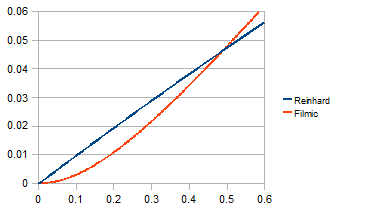
The classic choice is Reinhard tone mapping: $\text{out} = \frac{x}{1 + x}$. It is simple and guaranteed to never exceed 1.0. But it has a critical flaw: highlight desaturation. As values approach infinity, Reinhard converges to 1.0 for all channels, meaning bright, colorful objects become white.
ACES (Academy Color Encoding System) tone mapping, specifically the Narkowicz 2015 approximation, provides a much better result. It is the default tone mapper in Unreal Engine 4 and is used throughout the film industry:
vec3 acesTonemap(vec3 x) {
    float a = 2.51, b = 0.03, c = 2.43, d = 0.59, e = 0.14;
    return clamp((x * (a * x + b)) / (x * (c * x + d) + e), 0.0, 1.0);
}
| Property | Reinhard | ACES (Narkowicz) |
|---|---|---|
| Highlight color | Desaturates toward white | Preserves hue |
| Curve shape | Hyperbolic | Filmic S-curve (toe + shoulder) |
| Blacks | Linear | Lifted (cinematic look) |
| ALU cost | 3 ops | 8 ops |
| Used in | Academic, simple demos | UE4, film industry |
The 5 extra ALU operations are well worth the dramatically better color fidelity in boosted highlights.
HDR: When SDR Math Breaks Down
Everything above works correctly for SDR (Standard Dynamic Range) content encoded in BT.709/sRGB. But if you apply the same math to an HDR video (HDR10, HDR10+, HLG, Dolby Vision), the result will look radioactively wrong.
Why SDR Math Fails on HDR
HDR video stores pixel values using a non-linear Opto-Electronic Transfer Function (OETF). The two main OETF standards are:
- PQ (Perceptual Quantizer), defined by SMPTE ST 2084, used in HDR10/HDR10+/Dolby Vision. Optimized for human perceptual sensitivity. Maps 0–10,000 nits to code values.
- HLG (Hybrid Log-Gamma), defined by ARIB STD-B67, used in broadcast HDR. Backward-compatible with SDR displays.
When you multiply a PQ-encoded pixel by 1.2 to increase brightness by 20%, you are not making it 20% brighter. You are shifting it along a steep perceptual curve, potentially changing the brightness by 50% or more. Color grading math that assumes a linear or near-linear relationship between code values and perceived brightness produces wildly incorrect results.
The Grading Space Concept
The solution is to convert HDR content into a grading space where the color correction math behaves predictably (like SDR), apply the corrections, and convert back:
HDR OETF → Linear Light → Gamma 2.2 → [Color Grading] → Gamma 2.2⁻¹ → Linear Light → HDR OETF
vec3 toGradingSpace(vec3 c, int hdrMode) {
    if (hdrMode == 1) {         // PQ (HDR10)
        return pow(max(pqToLinear(c), 0.0), vec3(1.0 / 2.2));
    } else if (hdrMode == 2) {  // HLG
        return pow(max(hlgToLinear(c), 0.0), vec3(1.0 / 2.2));
    }
    return c;  // SDR: already in a suitable space
}

vec3 fromGradingSpace(vec3 c, int hdrMode) {
    if (hdrMode == 1) {
        return linearToPq(pow(max(c, 0.0), vec3(2.2)));
    } else if (hdrMode == 2) {
        return linearToHlg(pow(max(c, 0.0), vec3(2.2)));
    }
    return c;
}
The gamma 2.2 intermediate step is deliberate: it maps linear light into a perceptual space where the S-curve contrast, saturation mixing, and other operations produce visually consistent results regardless of whether the source is SDR or HDR. Without this step, the same contrast setting would look dramatically different on PQ vs. HLG vs. SDR content.
PQ Transfer Function (SMPTE ST 2084)
The PQ EOTF (Electro-Optical Transfer Function) is a complex polynomial designed to match human visual sensitivity:
const highp float PQ_M1 = 0.1593017578125;   // = 2610 / 16384
const highp float PQ_M2 = 78.84375;           // = 2523 / 32
const highp float PQ_C1 = 0.8359375;          // = 3424 / 4096
const highp float PQ_C2 = 18.8515625;         // = 2413 / 128
const highp float PQ_C3 = 18.6875;            // = 2392 / 128

highp vec3 pqToLinear(highp vec3 pq) {
    highp vec3 p = pow(max(pq, 0.0), vec3(1.0 / PQ_M2));
    highp vec3 num = max(p - PQ_C1, 0.0);
    highp vec3 den = PQ_C2 - PQ_C3 * p;
    return pow(max(num / den, 0.0), vec3(1.0 / PQ_M1)) * (10000.0 / 203.0);
}
Note the normalization factor 10000.0 / 203.0: PQ defines peak white at 10,000 nits, but the SDR reference white is 203 nits. This scaling ensures that SDR content and HDR content produce comparable values in the grading space.
HLG Transfer Function (ARIB STD-B67)
HLG uses a piecewise function: quadratic for shadows, logarithmic for highlights.
const highp float HLG_A = 0.17883277;
const highp float HLG_B = 0.28466892;
const highp float HLG_C = 0.55991073;

highp vec3 hlgToLinear(highp vec3 hlg) {
    bvec3 lo = lessThanEqual(hlg, vec3(0.5));
    highp vec3 branch_lo = hlg * hlg / 3.0;
    highp vec3 branch_hi = (exp((hlg - HLG_C) / HLG_A) + HLG_B) / 12.0;
    return mix(branch_hi, branch_lo, vec3(lo));
}
The mix with bvec3 is a branchless way to implement the piecewise function, again avoiding warp divergence on mobile GPUs.
Luminance Coefficients
HDR content uses the BT.2020 color space, which has different luminance coefficients than BT.709:
| Standard | R | G | B |
|---|---|---|---|
| BT.709 (SDR) | 0.2126 | 0.7152 | 0.0722 |
| BT.2020 (HDR) | 0.2627 | 0.6780 | 0.0593 |
Using the wrong coefficients in luminance calculations (saturation, vibrance, bilateral denoise) would produce incorrect results. The shader dynamically selects based on u_HdrMode:
vec3 W = (u_HdrMode != 0) ? LUMA_2020 : LUMA_709;
DRM: EGL Protected Content
One of the most common misconceptions in Android media development is that you cannot use OpenGL shaders with DRM-protected (Widevine L1) content. This is partially true and partially false.
What You Cannot Do
You cannot read pixel data back to the CPU. Calls like glReadPixels(), screenshot APIs, and SurfaceTexture.getTransformMatrix() + CPU-side buffer access will either fail or return black. This is by design. The content is protected.
What You Can Do
You can process protected textures entirely within the GPU, as long as the GPU never exposes the raw pixel data to non-secure memory. The mechanism is the EGL_EXT_protected_content extension.
To use it, three EGL components must be configured with the EGL_PROTECTED_CONTENT_EXT attribute:
| Component | What It Secures |
|---|---|
| EGL Context | GL commands execute in a secure GPU context |
| EGL Config | Framebuffer storage is in protected memory |
| EGL Window Surface | Display output goes through the secure path |
// Creating a secure EGL context
val contextAttribs = intArrayOf(
    EGL14.EGL_CONTEXT_CLIENT_VERSION, 2,
    EGL_PROTECTED_CONTENT_EXT, EGL14.EGL_TRUE,
    EGL14.EGL_NONE
)
val secureContext = EGL14.eglCreateContext(display, config, shareContext, contextAttribs, 0)

// Creating a secure window surface
val surfaceAttribs = intArrayOf(
    EGL_PROTECTED_CONTENT_EXT, EGL14.EGL_TRUE,
    EGL14.EGL_NONE
)
val secureSurface = EGL14.eglCreateWindowSurface(display, config, window, surfaceAttribs, 0)
With this setup, texture2D() calls in your fragment shader can sample the protected GL_TEXTURE_EXTERNAL_OES texture, apply all the color grading and sharpening math, and render to the secure surface, all without violating the DRM security model.
Caveat: Not all devices support EGL_EXT_protected_content. You need to check for the extension at runtime and fall back to the standard (unenhanced) rendering path on unsupported hardware.
Performance on Mobile GPUs
Frame Budget at 60fps
At 60fps, each frame must complete in 16.67ms. The video pipeline consumes a portion of this budget before our shader even runs:
SurfaceTexture.update: ~0.5ms
GL overhead (state, draw): ~0.5ms
────────────────────────────────
Available for shader: ~10-12ms
Shader Cost by Mode (4K, 8.3M fragments)
| Mode | Texture Fetches | ALU Ops | Adreno 730 (flagship) | Adreno 619 (budget) |
|---|---|---|---|---|
| Lightweight (color grading only) | 1 | ~20 | ~0.3ms (2.5%) | ~1.0ms (8%) |
| CAS + color grading | 5 | ~50 | ~1.5ms (12.5%) | ~4.5ms (37%) |
| CAS + Night Vision + grading | 14 | ~120 | ~3.5ms (29%) | ~10ms (83%) |
| Passthrough (disabled) | 1 | ~5 | ~0.1ms | ~0.3ms |
On flagship hardware, even the heaviest mode (14 texture fetches) fits comfortably within the 60fps budget. On budget hardware, CAS + Night Vision at 4K resolution pushes close to the 16.67ms limit. A quality tier system that disables Night Vision’s denoise pass on slow GPUs would be a practical mitigation.
Precision: mediump vs highp
Mobile GLSL offers two precision qualifiers that significantly affect performance:
mediump float: 16-bit floating point (FP16). Sufficient for color values (0.0–1.0 range). On Adreno/Mali, FP16 ALU runs at 2x the throughput of FP32.highp float: 32-bit floating point (FP32). Required for texture coordinates (UV), because UV precision errors at 4K resolution cause visible sampling artifacts (shimmer).
The optimal strategy: mediump for all color math, highp only for UVs and HDR transfer functions (which involve large intermediate values like 10,000 nits).
precision mediump float;                        // default: FP16 for colors
varying highp vec2 v_VideoTexCoordinate;         // FP32 for UV precision
Memory: Single-Pass, No FBO
The entire pipeline is a single draw call to a full-screen quad. There are no intermediate Framebuffer Objects (FBOs), no render-to-texture passes, and no off-screen buffers. The total additional memory footprint:
| Item | Size |
|---|---|
| 2 shader permutations (compiled) | ~10 KB |
| Vertex/texture coordinate buffers | ~100 B |
| Uniform values | ~200 B |
| Total | < 15 KB |
This is negligible. For comparison, a single 4K frame in RGBA8 is about 32 MB (3840×2160×4 bytes).
Thread Safety: The Volatile Snapshot Pattern
In a typical video player architecture, shader parameters are set from the UI thread (when the user adjusts a slider), but the shader runs on the GL thread. These threads run concurrently, and the parameters must be shared safely.
The solution uses a pattern that avoids locks entirely:
@Volatile
private var params: PostProcessParams = PostProcessParams.DEFAULT

// Called from UI thread
fun updateParams(newParams: PostProcessParams) {
    this.params = newParams  // single volatile write (atomic reference swap)
}

// Called from GL thread (onDrawFrame)
override fun onDrawFrame(gl: GL10?) {
    val snapshot = params  // single volatile read — snapshot for this frame
    // Use 'snapshot' for all uniform uploads — consistent values for entire frame
    GLES20.glUniform1f(brightnessLoc, snapshot.brightness)
    GLES20.glUniform1f(contrastLoc, snapshot.contrast)
    // ...
}
This works because:
PostProcessParamsis an immutable data class: once created, its fields never change- The
@Volatileannotation ensures the GL thread always sees the latest reference - The GL thread takes a local snapshot (
val p = params) and uses it for the entire frame, preventing torn reads mid-frame
No synchronized, no Lock, no AtomicReference. Just a single volatile read per frame. The JVM guarantees that reference writes are atomic on all architectures.
A/B Comparison Mode
A useful feature for tuning enhancement parameters is a split-screen comparison: the left half shows the original video, the right half shows the enhanced version, with a draggable divider line.
The shader implementation is minimal, just a single if statement at the top of main():
varying highp vec2 v_ScreenCoordinate;  // 0.0 (left) to 1.0 (right)
uniform int   u_ComparisonMode;
uniform float u_ComparisonPosition;     // divider position (0.0 - 1.0)

void main() {
    vec4 src = texture2D(videoTexture, v_VideoTexCoordinate);

    // Left of divider: show original, skip all processing
    if (u_ComparisonMode == 1 && v_ScreenCoordinate.x < u_ComparisonPosition) {
        gl_FragColor = src;
        return;
    }

    // Right of divider: apply full enhancement pipeline
    // ...
}
The v_ScreenCoordinate is computed in the vertex shader by remapping the clip-space position to [0, 1]:
v_ScreenCoordinate = position.xy * 0.5 + 0.5;
Note that the divider line itself is not drawn by the shader. It is rendered by a separate transparent overlay View on the UI thread. The GL thread and UI thread update at different rates, so if the shader drew the line, fast dragging would show two lines briefly out of sync. Letting the UI thread handle the visual divider exclusively eliminates this timing artifact.
Constraints and Limitations
| Content Type | Enhancement | Reason |
|---|---|---|
| SDR (non-DRM) | Supported | Standard GL pipeline |
| SDR + DRM | Supported | EGL_PROTECTED_CONTENT_EXT (if device supports it) |
| HDR (BT.2020) | Requires grading space conversion | Shader must handle PQ/HLG OETF round-trip |
| 360° / VR | Not applicable | Requires a separate projection renderer |
Wrapping Up
Building a real-time video enhancement pipeline on Android is a balancing act between visual quality and mobile GPU constraints. The key design decisions that make it practical:
- Shader permutations: pay for neighborhood operations only when needed (1 vs 5-14 texture fetches)
- S-curve contrast: smooth rolloff instead of linear clipping
- AMD CAS: content-adaptive sharpening that eliminates halos at the algorithm level
- Bilateral + ACES: physically-motivated denoising and tone mapping for Night Vision
- Grading space: HDR/SDR unified processing through OETF linearization
- Single-pass, no FBO: zero additional memory allocation
- Branchless mobile patterns:
smoothstepmasks instead ofifbranches
The total cost: 0.3ms for color grading only, 3.5ms for the full pipeline at 4K resolution on flagship hardware. Well within the 16.67ms frame budget.
The most important lesson is that mobile GPU optimization is fundamentally about texture fetches, not arithmetic. Every texture2D() call you can eliminate (by splitting into shader permutations, by choosing a 5-tap cross instead of a 9-tap box, by using smoothstep masks instead of conditional sampling) directly translates to real-world frame rate on real devices.
#android #opengl #glsl #video #gpu